Saturday, September 14, 2024

Installing Home Assistant on Armbian

 Those are the steps needed to install Home Assistant on Armbian 12 on any board (Orange PI PC):

  1.  Download the image of Armbian for you board
  2. In the shell write sudo su -
  3. Install the required libraries: 
    apt install apparmor bluez cifs-utils curl dbus jq libglib2.0-bin lsb-release network-manager nfs-common systemd-journal-remote systemd-resolved udisks2 wget -y
  4. Setting up NetworkManager, 
    1. sudo systemctl stop systemd-networkd
    2. sudo systemctl disable systemd-networkd
    3. sudo nano /etc/network/interfaces
      It should look like this:
      auto lo
      iface lo inet loopback
    4. sudo nano /etc/NetworkManager/NetworkManager.conf
    5. It should look like this:
      [main]
      plugins=ifupdown,keyfile
      [ifupdown]
      managed=true
    6. sudo systemctl reload NetworkManager
    7. sudo systemctl restart NetworkManager
    8. cd /etc/netplan/
    9. look for a single .yaml file edit it for example (10-dhcp-all-interfaces.yaml)
    10. in the line with "renderer: NetworkManager" change to NetworkManager, save and exit
    11. sudo netplan apply
    12. you might loose connectivity, do a sudo reboot
  5. Relogin to the server
  6. sudo nano /etc/os-release
  7. Change the line to look like this:
    PRETTY_NAME="Debian GNU/Linux 12 (bookworm)"
  8. save and exit
  9. sudo nano /boot/armbianEnv.txt
  10. at the end of the file add:
    extraargs=systemd.unified_cgroup_hierarchy=0
  11. save and exit
  12. sudo reboot
  13. sudo su -
  14. curl -fsSL get.docker.com | sh
  15. installing the OS-Agent
    1. follow the instructions, select your appropriate architecture (mine was armv7)
    2. check that it was installed correctly:
      gdbus introspect --system --dest io.hass.os --object-path /io/hass/os
    3. you should see some output
  16. the main install
    1. wget -O homeassistant-supervised.deb https://github.com/home-assistant/supervised-installer/releases/latest/download/homeassistant-supervised.deb
    2. apt install ./homeassistant-supervised.deb
    3. select "qemuarm" for armv7 in the selection list
    4. sudo systemctl enable hassio-apparmor.service
    5. sudo systemctl enable hassio-supervisor.service
  17. sudo reboot

Wait about 10 minutes for the dockers to spun up, and then you can access it http://<IP>:8123


Wednesday, July 26, 2023

DWR-921 C1/C3 OpenWRT Ordeal

Recently I've got my hands on a few DWR-921 routers with, those routers are nothing special

but they do have a 4G modem built-in so you can use them as a regular router or 4G one.


Checked the OpenWRT site and it is supported on the C1 and C3 revisions of the routers,
I had 4 C1 revision and 2 C3 revision.

after trying to put OpenWRT for a week this is what I've discovered,

There are 2 Flash layouts to these devices,

Older layout (Versions 1 - 3.0.0)
0x000000000000-0x000000010000 : "Bootloader" - JBOOT
0x000000010000-0x000000150000 : "Kernel"
0x000000180000-0x000000f10000 : "RootFS"
0x000000f10010-0x000000ff0000 : "UI"
0x000000ff0000-0x000001000000 : "Config"

Newer layout (Versions 3.0.X+)
mtd1: 00030000 00010000 "Bootloader" - UBOOT
mtd2: 00010000 00010000 "Config"
mtd3: 00010000 00010000 "Factory"
mtd4: 00150000 00010000 "Kernel"
mtd5: 00e60000 00010000 "RootFS"
mtd6: 00fb0000 00010000 "Linux"

Also each layout is supported by a different Bootloader (seems strange for D-Link to switch bootloaders on the same hardware)

OpenWRT only supports the older layout, so if you have update to a newer version of the Firmware
it will be much more difficult to downgrade and install OpenWRT.

UBOOT does not support OpenWRT in any shape or form, so lets see how to downgrade 
and what does JBOOT expects.


The JBOOT bootloader when loading looking for the Config memory space and it must be unmodified 
the CRC checks must be passed, without this partition the bootloader will not update to any version.

So if your Config partition is intact, you can hold reset on the device and turn it on, connect a computer with DHCP enabled and wait for the router to boot for a bit, navigate to any site and you will be redirected to firmware upload page, select the correct version of OpenWRT (C1/C3 with a -factory.bin ending)  and upload it you are done.

But you have a later version of the Firmware already installed, you will need a way to dump/flash the flash chip directly, something like CH341 device with the clip and the NeoProgrammer 2.X software 

First thing you do is backup your flash and save it in some place you remember.

Here is the firmware that you need to upload to your device using the programmer (unzip it first)
this firmware is for the C1 revision of hardware only, it will not work (for some reason on the C3)
The problem is there is no way that I've found to change the MAC address in the firmware since each update requires re calculating the CRC and editing it, after many tries I could not find how to correctly do it.

After flashing the firmware you can update to the OpenWRT version by holding Reset button and waiting for the process to start as written above.



Sunday, August 11, 2019

Reverse Engineering Smart Wristband LM707

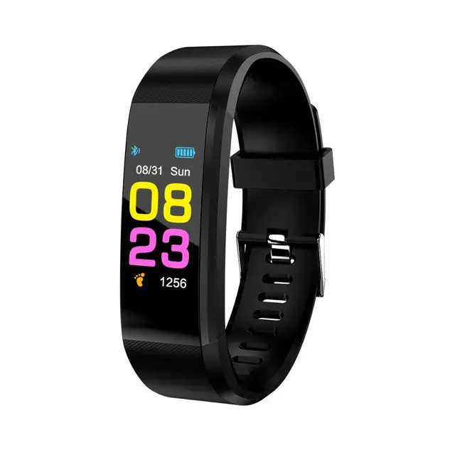
Recently bought a couple of "Smart bracelets"  LM707

to try RE so that I can put my own Firmware.
They have some nice features such as:
1. Color IPS LCD 80x160
2. Accelerometer
3. Pulse sensor
4. fast CPU...
5. BLE
6. Motor

I read some of articles about this and they usually have a NRF51/52 micro with BLE.
Sometimes they have the TLRS8266 by Telink.
So I thought get one open it up, see whats inside, *RE*, profit!

Got mine, opened it up and this what I got.
That weird chip is the MCU with markings 05PUN2 and a date code, and nothing else.

I had no idea what type of micro that is (still don't).
I've RE the APK that comes with it (luckily it was not protected), the app supports different types of 
MCUs (about 49 models), some are based on TELINK MCUs there are a mentions in the code.
and something called MAXSCEND, and this is what it's based on. 
No SDK no Datasheets, not info whatsoever, I have a method of uploading Firmware over OTP
(D/L of all the firmwares from the site). but they are of unknown Architecture so no idea.
I'm stuck, if anybody has any info, write in comments.

R.


Sunday, May 19, 2019

ESP8266 GameBoy Emulator, attempt.

I had an idea, to port a GameBoy emulator to an ESP8266 with an LCD screen.
found a good candidate for porting Peanut-GB, it's only a single file (.H) and with
plenty of examples.


Very little setup required and a single lcd_draw_line callback, implement LCD drawing
there and voila, GB emulator on the ESP8266 (node MCU clone), but it seems
the raw power of C is not sufficient for this task, and the LCD library
that I've chosen (TFT_eSPI) and modified was also insufficient to make
the emulator run at adequate speeds.

Games are stored in the flash using bin2hex.

The LCD in use is ST7789 based 240x240 connected to the SPI bus running at 40 Mhz.

Pinout:
NodeMCU - LCD
GND -> GND
3.3V -> VCC
3.3V -> BLK
D3 -> DC
D4 -> RES
D5 -> SCL
D7 -> SDA

So what do we have:
1. The emulator runs, tried with "super mario land", Tetris and a demo.
2. Uhm... Profit ?

What we don't have.
1. Good frame time, each frame takes between 70~200 ms which translates between 14~5 FPS.
2. Audio (There was not enough time for smooth frame rates.. so ...)
3. Key input (Yeah.. no..)


It seems that no matter how hard I tried to optimize the code the drawing part
would always lag, if we remove the LCD part, the core did have enough
time to emulate the game, but I think an emulator without a screen
is not a good emulator :)


What did I try to do:
1. ESP runs at 160 MHz, I can try to use NO_SDK (run at 340 Mhz) by CNLohr but the SPI bus is        affected by it.
2. Optimize the gb_draw_line up the wazoo, replaced all multiplications with right shifts.
3. Added per line hash drawing capabilities, so if the pixels of the line did not change, don;t draw            them, helpful with static games, not so much with scrolling.
4. Moving the game code to DRAM, did not produce significant speed ups. *
5. DynaRec? will probably require a lot of RAM and we have only 32000 bytes left.

* One of the issues that I've encountered is that the game needs to reside on the flash,  but because of alignment issues (the game is a an array of bytes [8-bit] but the memory of the ESP is 32Bit) the reading is slower.


Everything was developed using Sloeber, highly recommended for Android development.
Sources: primary project.
Sources: TFT_eSPI modified library
Hope that helps anybody.

R.

Thursday, November 29, 2018

Blue Pill (stm32f103c) as SPI programmer

I had a need to program SPI eeproms so looked around and found this for Arduino and off-course
it requires a 3.3V Arudino, I only had the Blue pill clone so I adapted the code and modified it
slightly to work with the pill attached is the connection schematics and code.

You will need to program the Pill with a bootloader for it to work as Arduino board.


Chip pinBlue pill pin
1 /SSPA4
2 MISOPA6
3 /WP+3.3V
4 GNDGND
5 MOSIPA7
6 SCKPA5
7 /HOLD+3.3V
8 VDD+3.3V

Also add a clip into the mix and create an ICSP.

You can use a serial console directly on the pill or the python script on the original repo
tested on Windows and Linux.

Code

Saturday, September 23, 2017

Modular Smart Array 500 G2 LCD - C51343NFU OPTREX

I was rummaging through my collection of old hardware and came across a HP storage module labeled:
HP StorageWorks
Modular smart array 500 G2

and it had a nice LCD on it so decided to see if we can use for something.

After extracting it, it became obvious that it was a separate module with:
* LCD
* Microcontroller
* buttons
* Dual color leds
* EEPROM memory

all in the small board !
Printed on the board :
C51343NFU
OPTREX Made in taiwan 284-3


Let the hacking commence.

So what's inside it:
* Microcontroller - PIC16F877 , (Not the A variant)
* LCD - HD44780 variance
* EEPROM - 24c32 I2C 4K
* 3 Dual color leds. (green and red)
2 - single leds, connected to the same output pin. (red)
A RC Oscilator of unknown speed.

That's great they even left pads for in circuit programming.

Here are the connections:

You will need an ICSP capable programmer, to program it.
Word of warning while programming, connect the 5V line to an external power source, most
programmers have insufficient current to supply the board.
I successfully programmed it with Pickit 3 and the Minipro programmer.

The LCD has weird display ROM the character map is "funky" to say the least, only space numbers and English letters are where they supposed to be, everything else requires some searching.


Attached is the source code which is in C, for MLAB X ide.
I have modified my version and added a 20Mhz crystal, I've removed a resistor (R24) from the RC circuit and added a resistor between MCLR and 5V, the code is written for the Crystal, should work for RC but the config bits need to be changed.

R.K.

Saturday, September 2, 2017

Orange PI PC + TFT ILI9341

Here is a quick way to configure a TFT display with a ILI9341 driver.
This should work with most (if not all) of Orange PI boards that are based on H3 (no Pi Zero).
I use Armbian as the OS.
such as:
to:

here are the connections that are needed:

Once connected, install Armbian for your board and connect to a network.
Find the IP of the device (connect to a screen and a keyboard, use the log of the router and etc.)
Putty/ssh to it, login (user: root pass:1234 , it's the default values - please change the password to something more secure)

The TFT screen should be ON (white or black screen) with nothing on it.

Create a new file /etc/modules-load.d/fbtft.conf with the following content:

fbtft_device

Create another file /etc/modprobe.d/fbtft.conf with the 
configuration for the fbtft_device device:

options fbtft_device custom name=fb_ili9341 gpios=dc:6,reset:9 speed=48000000 fps=25 busnum=0 rotate=270

restart device:
shutdown -r now

wait for boot,login again (the screen should be black)

Goto /etc/X11/xorg.conf and edit it, change the line that says
 Option                  "fbdev" "/dev/fb0"

to:
 Option                  "fbdev" "/dev/fb8"

And restart again,
shutdown -r now

When the device boots you should have a working screen.

Friday, February 17, 2017

RS232 to TTL level shifter using transistors

Here is a schematic for a convenient circuit to connect a micro to RS232 (COM) port using only common parts, no MAX232 and such.


BOM:
C1         220pF
D1         1N4007 - Can be almost any regular diode
J1         DB9
P1         CONN_4 - Can just use wires
Q1         BC558  -  PNP Transistor can probably use any PNP transistor
Q2         BC547 - NPN Transistor can probably use any NPN transistor
R1         10K
R2         10K
R3         10K
R4         3.3K
R5         3.3K
R6         3.3K

PIN 1 requires VCC the same voltage that the Microcontroller uses

Tested up to speeds 115200, used in many projects, ESP8266,sniffing router ports and the likes.

Friday, July 15, 2016

SDA5714 LED Display working with Arduino, with source

Found an old LED display from a Motorola MicroTAC with the markings SDA5714
Looked around the internet and found info mostly in Russian and with different code for atmel but not Arduino, decided to create a sketch with pinouts and a comprehensive example that uses both rows and the other LEDs (phone icon dots and etc), the font is implemented in the code, so you can modify it.
So here it is in action.


Pinout
Here is the Arduino Sketch
Hope that helps anybody.

Monday, January 28, 2013

Stellarplayer MOD & S3M module player

StellarPlayer V0.1
Finally SD support and multi-format support.

Added to the player:
1. Visualizer that uses the stellaris launchpad RGB (uses red and blue - left and right cahnnels)
2. S3M and MOD formats supported (detected by extension)
3. SD card support (using SPI mode on SSI0)

Limitations:
1. Because of the memory constraints the player only support up-to 14 channels mods
2. Some mod/s3m will not be able to played smoothly because our far buffers are quite small.
3. There are only 1100 bytes of free RAM left.
4. Put all the mods in a folder called "mods" in the root of the sd card
    I'm not sure fat32 is supported....

I've added a small LC filter to the output to limit the high frequency signals.
Here is a site that is help-full link , you don't have to use it but it gives a better sound.
(My cutoff frequency is 10Khz)

Schematics:
Audio: 
  • Left PB1
  • Right PB0
SD card:
  • SCK (clock) - PA2
  • CS (Chip select) - PA3
  • MOSI (Master out slave in - DI) - PA5
  • MISO (Master in slave out - DO) - PA4
Usage:
Right button next song, Left button previous song.

Sources and binary.


Wednesday, November 28, 2012

Stellaris Launchpad MOD Player

It is time for a new post!

Added SD Card, S3M and visualizer support see here link.

Recently I got myself a Stellaris Launchpad board by TI and thought what I could do with it.
I decided to create a simple MOD player with the bear minimum of extra parts and so here is the
result:

The details:
The code I've ported from a Microchip pic32 MIPS based MCU that was done here by SERVEURPERSO:
http://www.youtube.com/watch?v=i3Yl0TISQBE

Had to redo all the PWM/Timers/Buttons/File system and other stuff.
Learned a lot from the PWM tutorial for Stellaris here:
http://codeandlife.com/2012/10/30/stellaris-launchpad-pwm-tutorial/

The video recording was done using PC LINE IN and in stereo and because of that there is a faint whine in the background but the sound that comes directly from the board is much better.

The board supports only 4 channel MODs technically you can put a MOD with more channels but there is no memory allocated for them, so the results are unpredictable.
There is enough space on the device for 213Kb of MODs.
Right now the code is set to take up-to 6 MODS, you can change it if you want (as long as you keep below the 213Kb limit)

Because I did not have an SD card breakout board I had to load the files from somewhere
so I've created VFS (Virtual File System) which helped a lot during development, the files reside inside the
flash of the MCU.
It should be fairly easy to switch to FatFs since I've used the same prototype functions.

SD support will probably come in the future (when I get a SD breakout board)

Technical difficulties:
While porting this I've encountered several difficulties:
1. The amount of RAM on the pic32 device was 3 times what we had (96K vs our 32K)
     had to shrink the buffers a lot, will see how it affects while reading from SD card.
2. PWM code completely different, had to understand both architectures and settings to rewrite
    it correctly.
3. Timing for the sampler interrupt is CRITICAL even a small difference in invocation
    would cause popping and beeping in sound.
4. Interrupt priorities, after adding the buttons handling (which are polled using the systick interrupt) I've       noticed that the sound would be distorted, which I've concluded was due to the sampler interrupt not getting enough time to run or was itself was being interrupted, a code to set priorities to interrupts was added.

Hardware:
1 x Stellaris Launchpad
1 x Audio Jack

Schematics:
Take the audio jack connect the GND pin to the GND pin on the board J3.2
LEFT channel is J1.7 (PB4)
RIGHT channel is J2.7 (PB6)

Usage:
Right button next song
Left button previous song.

If connected to computer the serial terminal writes some info about the song that is playing.

File:
Attached is the whole project, source, binary and convert tool for mods.
Download project.

To use the convert tool: after extracting the project to Stellarisware directory.
NOTICE: My Stellarisware directory is called Stellarisware2 so some adjustments might be necessary in order to compile the sources, the project should be placed next to the other projects:
C:\StellarisWare2\boards\ek-lm4f120xl\modplayer

go into the tools directory copy all your wanted MODS to that dir and run "runconvert.bat"

To get more mods go to: http://modarchive.org/

Hope that helps anybody.
R.K.

Monday, June 11, 2012

Constellaris - A puzzle Game

Hello All,
I'ts been a while since I've posted last, but I've been busy writing my own game instead of
porting existing ones.

So here it is,
It's called Constellaris and it's for Android platform and now I'm going to shamelessly promote it...

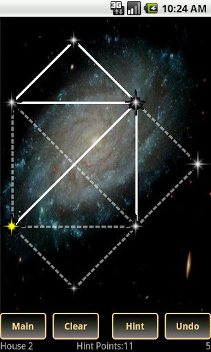
This is a simple puzzle game where you need to draw constellations (basically connect the dots)
You need to bridge two stars on screen without tracing back so that in the end 
you will have the same shape that is traced in the background.
Each level increases the level of difficulty.

You have a hints systems that helps you along the way if you get stuck and some options for convenience (Undo, clear and etc).


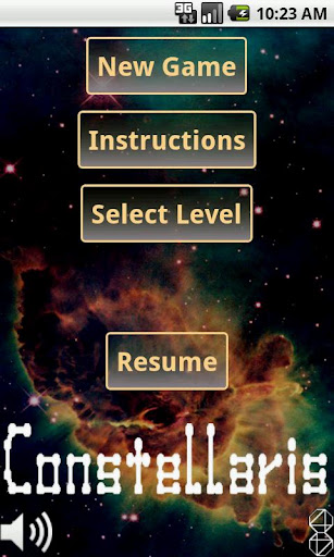
Menu Screen:
Inline image 1

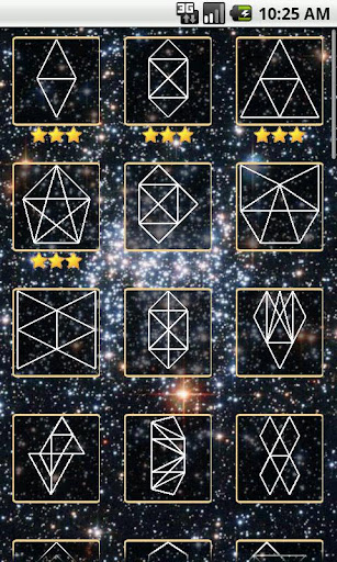
Level Selection:
Inline image 2

In game screen shoot:
Inline image 3

Video of the game play:

There are two versions free and paid, the difference is that the paid version has 27 more levels and no Ads.


Hope you like it.

You can also visit my site: http://www.octa44.com

Thanks!

Sunday, September 11, 2011

OpenXCom for Maemo (n900)

Hello,
OpenXCom is now available for N900


Port of OpenXCom (http://openxcom.org/) by Ronen K.

This is a port of the WIP OpenXCom engine remake

This port requires the original DOS files of X-Com.

You must create a directory called "openxcom" under your MyDocs folder
to there you must copy the original Dos files and extract this zip file
Than just use the icon to launch the game

To install type in X Term (While in root):
dpkg -i openxcom_0.3-1_armel.deb

to uninstall:

dpkg -r openxcom

Thanks to: OpenXCom.org and the team there!

Download Binary
Download Source

R.K.


Sunday, August 28, 2011

REminiscence (Flashback) for N900 (Maemo 5)

Hello,
Port of REminiscence is ready first version.


Download binary here
Download source here

To install type in X Term (While in root):
dpkg -i reminiscence_0.1-1_armel.deb

to uninstall:

dpkg -r reminiscence

This package requires the original Flashback files see readme below.


REminiscence for Maemo 5
-----------------------

You need to have
/home/user/MyDocs/FLASHDATA
and
/home/user/MyDocs/FLASHDATA/SAVES
folders the FLASHDATA folder should have the data files from flashback either
PC or Amiga versions are supported the mod files from the amiga version
can be used with the PC version, but a special naming scheme has to be used

You can use this in a batch file (Windows) to rename the amiga names
to the one supported by reminiscence then copy to FLASHDATA dir.

ren ascenseu.mod mod.flashback-ascenseur
ren ceinture.mod mod.flashback-ceinturea
ren chute.mod mod.flashback-chute
ren desinteg.mod mod.flashback-desintegr
ren donneobj.mod mod.flashback-donneobjt
ren fin.mod mod.flashback-fin
ren fin2.mod mod.flashback-fin2
ren gameover.mod mod.flashback-game_over
ren holocube.mod mod.flashback-holocube
ren introb.mod mod.flashback-introb
ren jungle.mod mod.flashback-jungle
ren logo.mod mod.flashback-logo
ren memoire.mod mod.flashback-memoire
ren missionc.mod mod.flashback-missionca
ren options1.mod mod.flashback-options1
ren options2.mod mod.flashback-options2
ren reunion.mod mod.flashback-reunion
ren taxi.mod mod.flashback-taxi
ren telepor2.mod mod.flashback-teleport2
ren telepora.mod mod.flashback-teleporta
ren voyage.mod mod.flashback-voyage


Keys:

Quit - Q button
Inventory\Skip Movie - Backspace
Operate / run / take - Hold Shift
Gun in/out - Space
Use Object - Enter

Thanks to: Gregory Montoir (http://cyxdown.free.fr/reminiscence)
for creating this great source.


Monday, August 22, 2011

Got new phone ... It's the N900..

Hello readers,

Good news I've got a new phone and it's the N900 probably the last great phone
from used to be all mighty Nokia.


Right now I'm in the process of acquainting myself with it's development environment
and probably soon will start porting stuff, hopefully some of you will find it useful.

R.K.

Sunday, June 12, 2011

I'm not dead, But Symbian is...

Hello everybody,

It's been a long time since my last update, there are few reasons for that.

I was working on my port and was almost at the end but encountered a very hard bug with
the sound system which was playing the sounds after a delay which made the game useless
and till this day I had not found a way how to fix this bug there
seems to be some problem with SDL_Mixer.

Nokia also has announced that they will stop supporting Symbian and switch to Windows platform.
There was also another company that did just that to survive but now is almost gone into obscurity, Palm.

These two factors together have demoralized me somewhat so right now porting has been halted.
I still have my n95, but the platform shows it's age which leaves me unwilling to support it for now.

R.K.

Tuesday, March 15, 2011

Dodgin diamonds II ported to Symbian s60 v3 Update

Hello,

A new version of DD2 is available,


Release 0.2(11)
This version has:
 * Fixed saves that were broken, please install on E drive.


Download


R.K.

Wednesday, March 9, 2011

Some updates

Hello all,
There have been very few updates lately because I'm working on a new port.
It is not one of the suggested one, but let me say this this is the first time this game has been
ported to any machine (it is originally ran in DOS) and the porting progress is very slow.
The game is quite old.

R.K.

Wednesday, March 2, 2011

Request for Port ideas

Hello everybody,

If you have an idea for a port post it here.
Please use these guide lines before considering a port:

1. The source code must be available. 
2. should be portable to 320x240 resolution. 
3. Remember we have very limited mouse support so not RTSs. 
4. Preferably SDL based games (but not a must) 
5. Not yet ported to symbian. 
6. Must be codded in C or C++ (no python, VB, C# or such nonsense) 
7. OpenGL is allowed (but this limits the target audience) 


R.K.

Sunday, February 27, 2011

Dodgin diamonds II ported to Symbian s60 v3

Hello,

I've finished porting DD2 (most of the work was already done by Anotherguest so thank him)


2d shot em up scroller.

To know more about this game please visit http://www.usebox.net/jjm/dd2/


Release 0.2(10) based on version 0.2.5 of DD2 by Anotherguest
This version has:
 * First release, Game functionality
 * configuration saves
 * Highscores
 * Game was tested on n95


Download game

Download source